


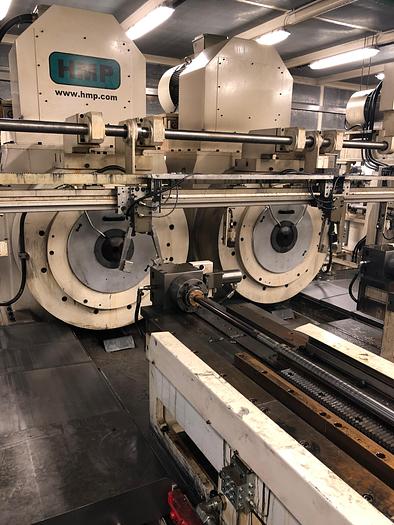
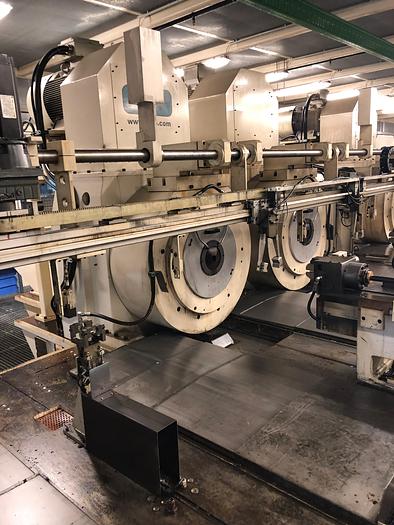
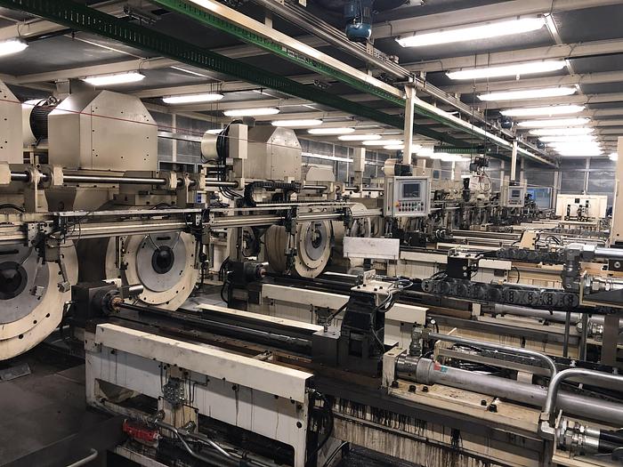
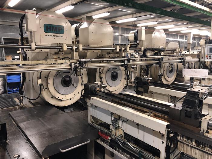
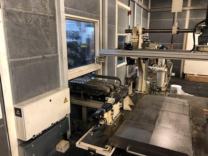
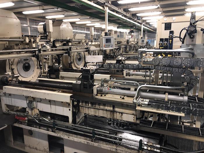
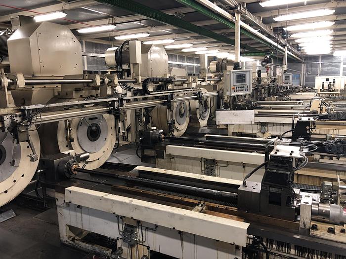
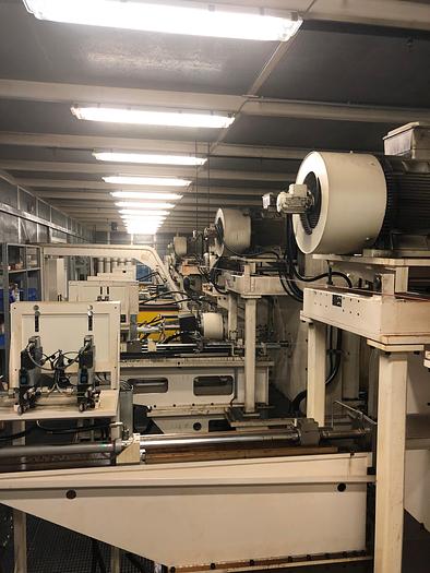
2014 HMP 16 STATION SWAGING LINE FOR AXLES AND OTHER LIKE SHAFTS
2014 HMP 16 STATION SWAGING LINE FOR AXLES AND OTHER LIKE SHAFTS
Available quantity: 1
Saginaw, MI
Description
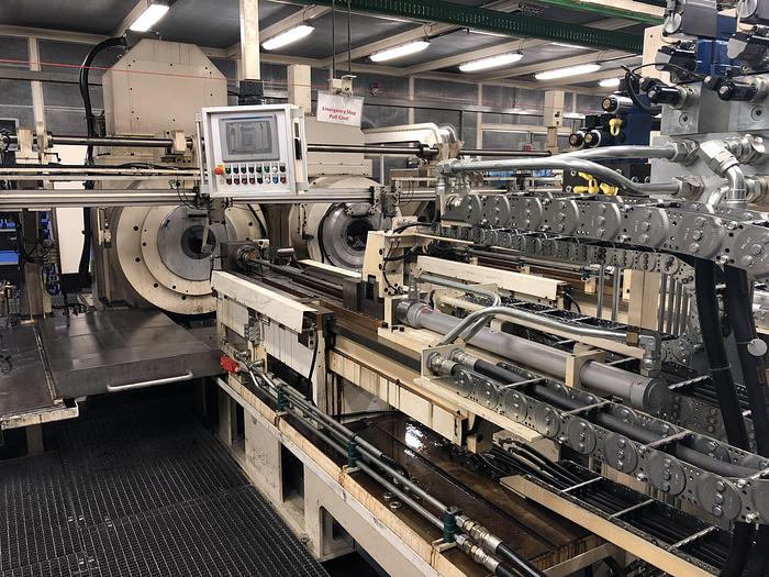
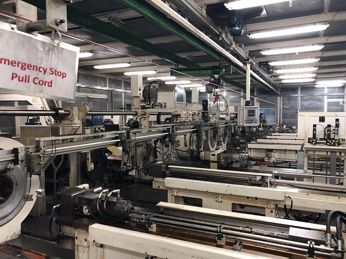
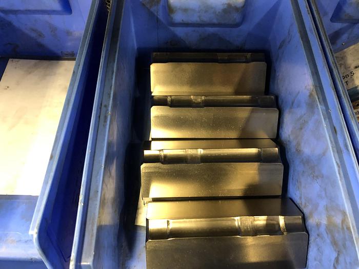
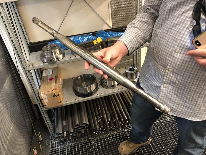
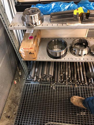
1-USED HMP SWAGING LINE FOR PRODUCING HOLLOW DRIVE SHAFT'S OR AXLES
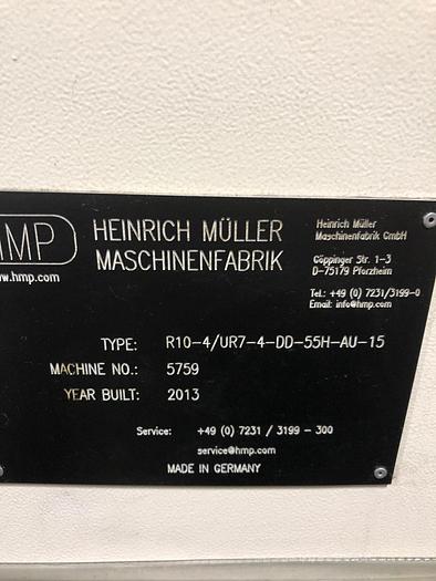
MACHINE SERIAL NUMBER R10-4/UR7-4-DD-55H-AU-13 MACHINE INSTALLED NEW 2014
STK#104013 ============================================================ SPECIFICATIONS WHILE OBTAINED FROM SOURCES DEEMED RELIABLE ARE SUBJECT CHANGE WITHOUT NOTICE AND TO VERIFICATION BY BUYER:
LINE IS OFFERED "AS-IS", WHERE-IS" BUYER RESPONSIBLE FOR
REMOVAL AND LOAD OUT. THIS ENTIRE LINE WAS INSTALLED IN 2014 WITH LIMITED USE AFTER INSTALL.
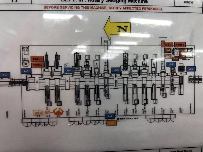
ONLY 350,000 AXLES WERE PRODUCED AFTER INSTALL. CAPACITY: CURRENTLY SET UP FOR 800MM LONG SHAFTS APPROX. DIAMETER CAPACITY 4" MAX. FOR FORMING HOLLOW OR SOLID SHAFT AXLES AND OTHER LIKE CYLINDRICAL FORMS MAJOR COMPONENTS OF THE LINE ARE AS FOLLOWS: 16-STATION TRANSFER SWAGING MACHINE R10-4/UR7-4-DD-55H-AU-13
equipped with:
-automation system
-station 0 transfer station
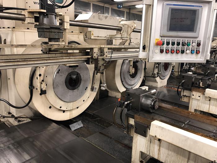
-station 1: swaging station R10-4
-station 2: swaging station R10-4
-station 3: transfer station
-station 4: swaging station R10-4
-station 5: swaging station UR7-4-DD
-station 6: hydraulic axial forming station HU-40
-station 7: turning station-sms
-station 8: turnaround station
-station 9: swaging station R10-4
-station 10: swaging station UR7-4-DD
-station11: swaging station UR7-4-DD
-station 12: axial forming station HU-40
-station 13: turning station
-station 14: rolling station
-station 15: cleaning station
-base, hydraulic system, lubrication system, PLC controls system, etc.
Additional Features, Options:
2.1 Noise and safety enclosure
2.2 Drip pan
2.3 Additional cleaning station
2.4 Additional neck down swaging station
Production Process on 13-Station Transfer Swaging Machine R10-4/UR7-4-DD-55H-AU-13
for example for Tubular Halfshaft Part No. 28130049
Station 1, reduce OD and wall in center section infeed
swaging R10-4 (parallel operation on stations 1 and 2)
Station 2, reduce OD and wall in center section infeed
swaging R10-4 (parallel operation on stations 1 and 2)
Station 3, station to load parts from station 1 or
transfer station from station 2 into station 4
Station 4, pre-form form first end infeed swaging R7-4
Station 5, finish form first end plunge swaging
UR7-4-DD
Station 6, external spline first end axial forming
HU-40
Station 7, face and chamfer first end, turn and deburr
turning groove in spline area
Station 8, turn shaft 180°
turnaround station
Station 9, pre-form second end infeed swaging R7-4
Station 10, finish form second end plunge swaging
UR7-4-DD
Station 11, external spline second end axial forming
HU-40
Station 12, face and chamfer second end, turn and deburr
turning groove in spline area
Station 13, boot grooves both sides rolling
Remarks: OD and wall reduction in center section is
carried out in simultaneous operation on stations 1 and 2 in order to reduce total cycle time for
this longest operation (approx. 35 sec. per op. I station) to 50%, thus cycle time of entire
transfer line corresponds to shorter cycle time (18 sec.) of stations 4 - 13
Cycle time: 18 seconds per piece - (reference this time as per Nexteers' piece part)
13-Station Transfer Swaging Machine R10-4/UR7-4-DD-55H-AU-13:
1.1 Automation System:
1.1.1 Bunker:
Installed in front of the input conveyor outside of the noise and safety
enclosure (see additional features below).
Capacity about 120 pieces with outside diameter 044 mm.
Equipped with loading device to separate the workpieces and to transfer them onto the input
conveyor.
1.1.2 Transfer System:
Linear transfer system for automatic workpiece transport from the input conveyor
into station 1 and 2 (parallel operation), from station 1 or 2 into station 3 (transfer
station), and simultaneously from station 3 - 13 and from the last station to the machine exit.
All transfer grippers are hanging vertically from top to bottom.
The transfer system can be pivoted up for tool change, maintenance, etc.
1.1.3 Conveyors:
1.1.3.1 Input Conveyor:
Conveyor to transport the workpieces from outside the noise and safety enclosure into
the first transfer gripper of the machine.
1.1.3.2 Exit conveyor:
Conveyor to transport the workpieces from the machine to the outside of the noise and
safety enclosure.
The conveyor can be inclined to drain off lubrication oil from the inside and outside
of the workpiece.
1.2 Station 1: Swaging Station R10-4
1.2.1 Swaging machine R10-4:
Infeed swaging machine for axial infeed swaging operations.
Internal rotating machine with rotating spindle and stationary outer ring.
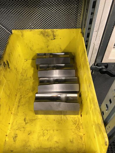
Heavy-duty 4-die swaging machine with dies dimension 100 x 100 x 250 mm (width x height x
length).
Actively driven cage rollers for high output and reduced wear.
1.2.1.1 Hydraulic counter-pusher / mandrel device installed at the rear of the swaging
machine, device reaching through the machine spindle.
Equipped with linear encoder for control of the positions (programmable).
1.2.2 Feeding system:
Hydraulic feeding system type 55H for workpiece infeed.
Equipped with linear encoder and servo-hydraulic cylinder for control of the
positions (programmable) and speeds (programmable).
1.2.2.1 Feeder jaw:
Hydraulic workpiece clamping device with two radial parallel jaws on the slide
of the feeding system.
The clamping pressure is continuously adjustable for controlled rotational
speed of the workpiece during swaging.
1.2.2.2 Mandrel device:
Hydraulic mandrel device on the slide of the feeding system.
Mandrel device used for calibration of workpiece bore sizes, for wall thickness
reductions, and for swaging of internal profiles with tight tolerances.
Equipped with linear encoder for control of the positions (programmable).
1.3 Station 2: Swaging Station R10-4
Station identical to station 1, see item 1.2
1.4 Station 3: Transfer Station
Station to take over the parts from station 1 or station 2 (parallel operation)
from the first unit of the transfer system and to transfer them into the second
unit of the transfer system for loading into station 3.
1.5 Station 4: Swaging Station R7-4
1.5.1 Swaging machine R7-4:
Infeed swaging machine for axial infeed swaging operations.
Internal rotating machine with rotating spindle and stationary outer ring.
Heavy-duty 4-die swaging machine with dies dimension 70 x 70 x 150 mm
(width x height x length).
Actively driven cage rollers for high output and reduced wear.
1.5.1.1 Hydraulic counter-pusher / mandrel device installed at the rear of the swaging
machine, device reaching through the machine spindle.
Equipped with linear encoder for control of the positions (programmable).
1.5.2 Feeding system:
Hydraulic feeding system type 55H for workpiece infeed.
Equipped with linear encoder and servo-hydraulic cylinder for control of the
positions (programmable) and speeds (programmable).
1.5.2.1 Feeder jaw:
Hydraulic workpiece clamping device with two radial parallel jaws on the slide
of the feeding system.
The clamping pressure is continuously adjustable for controlled rotational
speed of the workpiece during swaging.
1.5.2.2 Mandrel device:
Hydraulic mandrel device on the slide of the feeding system.
Mandrel device used for calibration of workpiece bore sizes, for wall thickness
reductions, and for swaging of internal profiles with tight tolerances.
Equipped with linear encoder for control of the positions (programmable).
1.6 Station 5: Swaging Station UR7-4-DD
1.6.1 Swaging machine UR7-4-DD:
Plunge swaging machine for radial plunge swaging operations and for axial
infeed swaging operations.
Double-rotating machine with rotating spindle and rotating outer ring.
Heavy-duty 4-die swaging machine with dies dimension 70 x 70 x 150 mm
(width x height x length).
Actively driven cage rollers for high output and reduced wear.
Machine equipped with locking system for the spindle enabling to produce also
non-circular external cross-sections.
Hydraulic plunging device for opening and closing the swaging dies radially.
The radial movement of the swaging dies is executed by moving the tapered
outer strikers axially along the tapered axially stationary wedges (patented).
When the plunging device remains stationary (by selecting the corresponding
machine program), the machine can alternatively also be employed as an
infeed swaging machine.
Outer strikers and swaging dies are mechanically linked (patented).
The strikers have a special movement which separates the strikers from the
rollers when the dies are radially open, thereby no noise and no wear when the
machine is idling (patented).
Equipped with linear encoder and servo-hydraulic cylinder for control of the
closing and opening positions (programmable) and speeds (programmable) of
the plunging device.
1.6.1.1 Hydraulic counter-pusher / mandrel device installed at the rear of the swaging
machine, device reaching through the machine spindle.
Equipped with linear encoder for control of the positions (programmable).
1.6.2 Feeding system:
Hydraulic feeding system type 55H for workpiece infeed.
Equipped with linear encoder and servo-hydraulic cylinder for control of the
positions (programmable) and speeds (programmable).
1.6.2.1 Feeder jaw:
Hydraulic workpiece clamping device with two radial parallel jaws on the slide
of the feeding system.
The clamping pressure is continuously adjustable for controlled rotational
speed of the workpiece during swaging.
1.6.2.3 Slide lock:
Hydraulic device to lock the feeder slide axially during plunge swaging to
obtain precise swaging positions.
1.7 Station 6: Hydraulic Axial Forming Station HU-40
1.7.1 Forming unit HU-40:
Horizontal hydraulic forming cylinder with die retainer to take up one external
forming die for example for production of external splines.
System for easy and quick exchange of the forming die.
Linear encoder and servo-hydraulic cylinder for control of the positions
(programmable) and speeds (programmable) of the forming die.
Max. forming force: 400 kN
Max. forming stroke: 150 mm
1.7.1.1 Mandrel device installed at the rear of the forming unit.
Concentric system through the piston of the main forming cylinder.
The mandrel is used for calibration of the inside diameter under the externally
formed (spline) workpiece area.
1.7.2 Clamping device:
Hydraulic radial clamping device for concentric clamping of the workpiece
directly in front of the forming area.
The clamping device is rigidly connected with the forming unit via four columns.
1.7.3 Feeding system:
Hydraulic feeding system for loading the workpieces into the radial clamping
device.
Equipped with linear encoder and servo-hydraulic cylinder for control of the
positions (programmable) and speeds (programmable).
1.7.3.1 Feeder jaw:
Hydraulic workpiece clamping device with two radial parallel jaws on the slide
of the feeding system.
The clamping pressure is continuously adjustable.
1.8 Station 7: Turning Station
Turning station for facing and chamfering of the workpiece end, for production
of circular grooves and undercuts and for deburring of turned grooves in
external splines.
(NOTE TO BUYER. THIS STATION WAS UPGRADED TO SMS TURNING STATION. )
1.8.1 Turning unit:
Unit operating with rotating workpiece and stationary tooling.
Equipped with rotationally driven chuck to clamp and rotate the workpiece
during the turning operation. The rotational speed of the chuck is electronically
adjustable.
Slide unit for end facing and chamfering and for production of grooves.
One radial slide with deburring wheel for removal of burrs on turned grooves
located in the area of external splines.
The infeed positions and speeds of the cutting slides are programmable.
(NOTE TO BUYER. THIS STATION WAS UPGRADED TO SMS TURNING STATION.)
1.8.2 Feeding system:
Feeding system for infeed and outfeed of the workpieces into the chuck.
Adjustable quick speed and slow speed for both movement directions.
The feeder movements are programmable.
1.8.2.1 Hydraulic workpiece clamping device with two radial jaws installed on the slide
of the feeding system.
1.8.3 Magnetic chip removal conveyor installed at the rear of the turning unit.
1.9 Station 8: Turnaround Station
Station to change the workpiece orientation 180° after forming the first
workpiece end on stations 1-7 for processing of the opposite, second
workpiece end on stations 9-13.
Equipped with rotation cylinder with gripper, and with axial positioning cylinder
to move the workpiece into a defined axial position after rotation.
1.10 Station 9: Swaging Station R7-4
Station identical to station 4, see item 1.5
1.11 Station 10: Swaging Station UR7-4-DD
Station identical to station 5, see item 1.6
1.12 Station 11: Hydraulic Axial Forming Station HU-40
Station identical to station 6, see item 1.7
Page 10 of 14
1.13 Station 12: Turning Station
Station identical to station 7, see item 1.8
(NOTE TO BUYER. THIS STATION UPGRADED TO SMS TURNING STATION)
1.14 Station 13: Rolling Station
Station for simultaneous rolling of boot grooves on both workpieces ends.
1.14.1 Double-sided rolling unit with rolling head mounted on a robust spindle unit.
Hydraulic slide units for axial positioning of the rolling units over the workpiece
ends, with adjustable and programmable speeds and positions.
1.14.2 Hydraulic workpiece clamping device.
1.15 Machine base.
1.16 Hydraulic power station at the side of the machine.
Oil tank equipped with heat exchanger oil / water and with oil heating.
Central unit with 5 zones.
1.17 System for operation under oil-flush, with oil tank, pump, filters, heat exchanger
oil / water and oil heating.
1.18 Centralized lubrication system for all slides.
1.19 Electrical cabinet at the side of the machine.
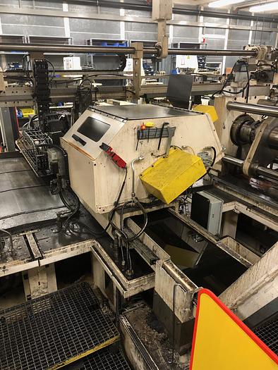
PLC controls system for control of all positions and movements.
Programs for setting and for automatic operation.
1.20 Machine monitoring and diagnostic system on the control panel.
Display text in English language.
1.21 Machine capable of producing workpieces within the following dimensional
range (other dimensions are possible within certain limits, to be discussed):
- outside dia. of input part: min. 30.0 mm max. 55.0 mm
- workpiece length: min. 350 mm max. 900 mm
1.22 Equipment components (details to be discussed):
- PLC: Allen-Bradley
- Operator panel: Allen-Bradley
- Electric motors: Siemens
- Proximity switches: Balluff
- Hydraulic components: Vickers
- Hydraulic cylinders: HMP, Hänchen
- Pneumatic components: Festo
- Central lubrication system: Willy Vogel or Trabon
2. Additional Features: Fire suppression installed at Nexteer.
2.1 Noise and safety enclosure:
Enclosure covering the entire machine. The enclosure is used to reduce the
noise level and simultaneously also acts as safety device according
international safety standards.
Equipped with doors for access to the machine and with windows for visual
control. The doors are equipped with safety switches.
Equipped with lighting and with fans for exchange of air.
Max. noise level outside in about 1 m distance from the enclosure:
80 dB (A) during automatic machine operation
2.2 Drip pan with floor gratings:
Drip pan covering the entire floor surface area inside the enclosure, with floor
gratings in the areas between machine and enclosure walls.
2.3 Additional cleaning station:
Additional station installed at the last position of the transfer line.
Air blow off system for internal and external removal of oil on and inside the
workpiece. No dripping after cleaning. Achieved by vacuum system.
Oil is then returned to central coolant system.
2.4 Additional neck down swaging station:
Additional swaging station installed after station 2 to neck down the center
section of halfshafts from 36 mm OD to 28 mm OD, 63.36 mm long.
Plunge swaging station UR7-4-DD, identical to station 5, see item 1.6
This is included as station 11.
2.5 Overhead Crane for change over.
2.6 Note to Buyer. The fire suppression system installed by Nexteer will
only include the parts of the system that installed inside the enclosure.
No external components are included in the sale. Buyer may be able
to hook up fire suppression system inside the room which is included in the
sale to their own central in plant system.
REMOVAL:
Removal of HMP swaging line to take place within 30 days from date of sale.
STORAGE:
Storage if required after removal and prior to shipment can be arranged
some storage space is available at Nexteer in Saginaw, MI at no additional costs
to buyer. Transportation costs to Storage Location is the buyer's responsibility.
Storage time is limited and to be used as a buffer as buyer continues with timely
removal and shipment of all components and related equipment to their facilities.
PAYMENT TERMS:
Buyer shall pay 50% of purchase price prior to start of Removal.
Ownership/Title for the equipment will pass to Buyer upon receipt of the initial 50% down payment with order.
Remaining 50% shall be paid prior to the Property being removed from Nexteer Facility.
THIS ITEM IS OFFERED FOR SALE SUBJECT TO PRIOR SALE AND
BUYER'S UNCONDITIONAL ACCEPTANCE OF SELLERS TERMS
AND CONDITIONS.
RAB INDUSTRIES, INC.
Specifications
| Manufacturer | HMP |
| Model | HMP SWAGING LINE |
| Year | 2015 |
| Condition | Used |
| Serial Number | R10-4/UR7-4-DD-55H-AU-13 |
| Stock Number | 104013 |
| Station 1 | swaging station R10-4 |
| Station 2 | swaging station R10-4 |
| Station 3 | transfer station |
| Station 4 | swaging station R10-4 |
| Station 5 | swaging station UR7-4-DD |
| Station 7 | turning station-sms |
| Station 8 | turnaround station |
| Station 9 | swaging station R10-4 |
| Station 10 | swaging station UR7-4-DD |
| Station11 | swaging station UR7-4-DD |
| Station 12 | axial forming station HU-40 |
| Station 13 | turning station |
| Station 14 | rolling station |
| Station 15 | cleaning station |
| 1.2 Station 1 | Swaging Station R10-4 |
| 1.3 Station 2 | Swaging Station R10-4 |
| 1.4 Station 3 | Transfer Station |
| 1.5 Station 4 | Swaging Station R7-4 |
| 1.6 Station 5 | Swaging Station UR7-4-DD |
| Max. forming force | 400 kN |
| Max. forming stroke | 150 mm |
| 1.8 Station 7 | Turning Station |
| 1.9 Station 8 | Turnaround Station |
| 1.10 Station 9 | Swaging Station R7-4 |
| 1.11 Station 10 | Swaging Station UR7-4-DD |
| 1.13 Station 12 | Turning Station |
| 1.14 Station 13 | Rolling Station |
| PLC | Allen-Bradley |
| Operator panel | Allen-Bradley |
| Electric motors | Siemens |
| Proximity switches | Balluff |
| Hydraulic components | Vickers |
| Hydraulic cylinders | HMP, Hänchen |
| Pneumatic components | Festo |
| Central lubrication system | Willy Vogel or Trabon |
